04 - Tuning and Moving
Introduction
In this tutorial, we will be learning how to tune the PIDs, move the robot autonomously, and use odometry.
Odometry
As mentioned in the previous tutorial, LemLib uses odometry to track the position of the robot. However, we need to calibrate it at the start of each match. To do this, we need to call the lemlib::Chassis::calibrate() function in initialize() Below is an example of how to do this:
void initialize() {
    chassis.calibrate();
}
Note that the chassis should be stationary when you call this function. It will take 3 seconds to calibrate, so don’t be alarmed if it doesn’t seem to be doing anything.
Pretty simple, right? Now, we can use the lemlib::Chassis::getPose() function to get the current position of the robot. It returns a lemlib::Pose object, which contains the x, y, and heading. The code below uses the lemlib::Chassis::getPose() function to constantly print the current position of the robot to the brain screen:
void initialize() {
    pros::lcd::initialize(); // initialize brain screen
    chassis.calibrate(); // calibrate sensors

    // print odom values to the brain
    pros::Task screenTask([&]() {
        while (true) {
            lemlib::Pose pose = chassis.getPose(); // get chassis position
            pros::lcd::print(0, "X: %f", pose.x);
            pros::lcd::print(1, "Y: %f", pose.y);
            pros::lcd::print(2, "Theta: %f", pose.theta);
            pros::delay(10);
        }
    });
}
We can also set the position of the robot using the lemlib::Chassis::setPose() function. Below is an example of how to do this:
void autonomous() {
    // this is where the robot start in auton
    // X: 5.2, Y: 10.333, Heading: 87
    chassis.setPose(5.2, 10.333, 87);
}
It is highly recommended you set the starting position of the robot for each autonomous. Otherwise you won’t be able to take advantage of the visualization in the path generator.
Moving with turnTo, moveToPoint, and moveToPose
LemLib has 4 functions for moving the robot. We will be covering the first 3 in this tutorial, and the forth in the next tutorial.
The first function is lemlib::Chassis::turnTo(). This function turns the robot so that it is facing the specified (x, y) point. It takes between 3 and 5 arguments. It uses the PID gains specified in the lateralController struct. Below is an example of how to use it:
void autonomous() {
    // turn to the point (53, 53) with a timeout of 1000 ms
    chassis.turnTo(53, 53, 1000);
    // turn to the point (-20, 32) with the back of the robot facing the point, and a timeout of 1500 ms
    chassis.turnTo(-20, 32, 1500, true);
    // turn to the point (10, 0) with a timeout of 1000 ms, and a maximum speed
    // of 50, with the front of the robot facing the point
    chassis.turnTo(10, 0, 1000, false, 50);
}
As you can see, using this function is very easy. The first 2 parameters are the X and Y location the robot should be facing. The third parameter is the timeout, which is the maximum time the robot can spend turning before giving up. The fourth parameter is whether the back of the robot should face the point (true) or the front of the robot should face the point (false). It defaults to false if not specified. The fifth parameter is the maximum speed the robot can turn at. If you don’t specify a value for this parameter, the robot will turn at full speed.
The second function is lemlib::Chassis::moveToPoint. This function moves the robot to the specified (x, y) point. It takes 3 or 4 arguments. It uses the PID gains specified in the lateralController and angularController struct. Below is an example of how to use it:
void autonomous() {
    chassis.moveTo(53, 53, 1000); // move to the point (53, 53) with a timeout of 1000 ms
    chassis.moveTo(10, 0, 1000, 50); // move to the point (10, 0) with a timeout of 1000 ms, and a maximum speed of 50
}
This function is similar to the lemlib::Chassis::turnTo() function. The first 2 parameters are the X and Y location the robot should move towards. The third parameter is the timeout, which is the maximum time the robot can spend turning before giving up. The fourth parameter is the maximum speed the robot can move at. If you don’t specify a value for this parameter, the robot will move at full speed.
The third function is lemlib::Chassis::moveToPose(). This function moves the robot to the specified (x, y) point with the addition of a target heading in degrees. It uses the PID gains specified in the lateralController and angularController struct. Below is an example of how to use it:
void autonomous() {
    // move to the point (53, 53) at heading 90 with a timeout of 1000 ms
    chassis.moveToPose(53, 53, 90, 1000);
    // move to the point (10, 0) at heading 270 with a timeout of 1000 ms.
    // Move in reverse
    chassis.moveToPose(10, 0, 270, 1000, false);
}
This function is very similar to the lemlib::Chassis::moveToPoint() function. The first 3 parameters are the x, y, and heading the robot should move to. The fourth parameter is the timeout, which is the maximum time the robot can spend turning before giving up. The fifth parameter is whether the robot should move backwards or forwards. The fifth parameter is the maximum speed the robot can move at. Only the first 4 parameters are required.
Understanding asynchronous movements
By default all movements in LemLib run asynchronously. Put plainly, it runs in its own task. While the system is robust, it takes a little getting used to. Let’s look at some examples:
pros::millis(); // returns 0000
chassis.moveToPose(0, 0, 0, 1000);
pros::millis(); // returns 0000
As you can see, function calls after a movement function call are ran immediately afterwards. However, it will wait until the current movement is done before calling the next movement call. Lets look at the next example:
pros::millis(); // returns 0000
chassis.moveToPose(0, 0, 0, 1000);
pros::millis(); // returns 0000
chassis.moveToPose(0, 0, 0, 1000);
pros::millis(); // returns 1000
The program waits. But what if we want to wait until the robot has moved a certain distance? Well, there’s a function for that
pros::millis(); // returns 0000
chassis.moveToPose(0, 20, 0, 1000);
chassis.waitUntil(10); // wait until the chassis has traveled 10 inches
pros::millis(); // outputs 500
chassis.waitUntilDone(); // wait until the movement has been completed
pros::millis(); // outputs 1000
IMPORTANT NOTE
lemlib::Chassis::waitUntilandlemlib::Chassis::waitUntilDonework for all movements. The only difference is when you are usingchassis.turnTo, where instead of inches the units are in degrees.
This system will take a bit of getting used to, but it is very powerful. If you need additional examples, check out the example project, open a discussion, or open a ticket in our Discord server.
Tuning the PIDs
Now that we know how to move the robot, we can start tuning the PIDs. Let’s start with the lateral PIDs.
The lateral PID is just a simple PD controller, with some minor optimizations. When we tune the lateral PD, we want the kP as high as possible with minimal oscillation. But how do we change these gains? The answer is the lateralController struct we created in the previous tutorial. Here is a reminder of what it looks like:
// forward/backward PID
lemlib::ChassisController_t lateralController {
	10, // kP
	30, // kD
	1, // smallErrorRange
	100, // smallErrorTimeout
	3, // largeErrorRange
	500, // largeErrorTimeout,
    20 // slew (maximum acceleration)
};
The first 2 parameters are the kP and kD gains. These are the ones we will be focusing on for now. When we tune them, we want kP as high as possible with minimal oscillation (the robot moving backwards/forwards repeatedly at the end). Here is the method we will be using to tune these gains:
Move the robot 10 inches forward using the
lemlib::Chassis::moveToPose()function.Increase kP until the robot starts oscillating.
Increase kD until the oscillation stops.
Record kP and kD values.
Repeat steps 2-4 until you can’t stop the oscillation. At this point, use the last kP and kD values you recorded.
After this, you need to tune the slew rate. This controls the maximum acceleration of the chassis in order to prevent tipping. To tune it, simply increase it until the robot starts tipping too much. Higher values make the robot accelerate faster, and slower values make the robot accelerate slower.
The process for the angular PID is very similar. Here is a reminder of what the angular PID looks like:
// turn PID
lemlib::ChassisController_t angularController {
    2, // kP
    10, // kD
    1, // smallErrorRange
    100, // smallErrorTimeout
    3, // largeErrorRange
    500, // largeErrorTimeout
    80 // slew (maximum acceleration)

};
Here is the algorithm we will be using to tune these gains:
Turn the robot to face (30, 0) using the
chassis.turnTo()function with the robot starting at (0, 0).Increase kP until the robot starts oscillating.
Increase kD until the oscillation stops.
Record kP and kD values.
Repeat steps 2-4 until you can’t stop the oscillation. At this point, use the last kP and kD values you recorded.
Optional - Tuning Timeouts
You may have noticed that there are 4 more values in the angularController and linearController structs. These are values for the timeouts. Here is how they work:
smallErrorRangeis the range of error that is considered “small”. If the error is within this range forsmallErrorTimeoutmilliseconds, the robot will proceed to the next movementlargeErrorRangeis the range of error that is considered “large”. If the error is within this range forlargeErrorTimeoutmilliseconds, the robot will proceed to the next movement
The units for error in the chassis.moveToPose() function are inches, and degrees for the chassis.turnTo() function. The units for time are milliseconds.
Advanced users may wish to alter these values to decrease the time it takes to execute the next command. However, the default values should be fine for most users.
Using the Path Generator for Coordinates
You may be wondering how we know what coordinate the robot start at, and what the location is of a specific object (e.g a goal). Thankfully, it is very easy. You can use this software. Just hover your mouse over a location on the field, and you will see the coordinates of the mouse on the field. Refer to the image below:
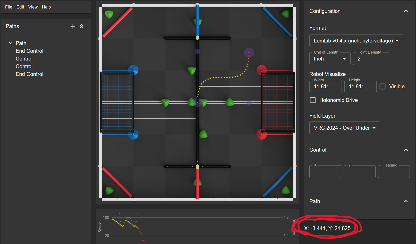
You can use these coordinates to set the starting position of the robot, and use them with the lemlib::Chassis::turnTo(),lemlib::Chassis::moveToPoint() and lemlib::Chassis::moveToPose() functions.
Note that the origin of the field is in the middle, and the field coordinates are measured in inches. 0 degrees is facing up, and increases clockwise.
Thats it! You now know how to move the robot around the field using the lemlib::Chassis::turnTo(),lemlib::Chassis::moveToPoint() and lemlib::Chassis::moveToPose() functions. In the next tutorial, we will be covering how to use the Path Generator to create a path for the robot to follow.